Evo M51 Quick Start Guide

1 Introduction
The Evo M51 module marks the evolution of Alorium Technology’s FPGA enhanced microcontroller solutions.
By pairing a powerful Microchip (Atmel) 32-bit SAMD51 microcontroller with the low-cost, highly-featured Intel MAX 10 FPGA, Evo M51 provides the perfect blend of embedded compute performance and flexibility.
With the increasingly popular Adafruit Feather form factor and pinout plus an additional 34 castellated edge I/O, this board can be easily added into existing projects or directly integrated into new system designs as compute module component.
This quick start guide will help you get up and running quickly with your Evo board!
2 Pinouts
Evo M51 was designed for compatibility with the Adafruit Feather specification for primary I/O and connectivity. As a result, all of the through-hole I/O on Evo match what you should find with any other Feather-compatible board.
In addition to the standard Feather I/O, Evo includes 34 castellated vias which can be used as digital I/O.
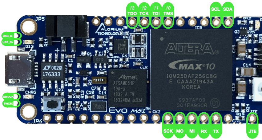
2.1 Pin Map
The following diagram shows the pin assignments for Evo M51. Click here or on the image below to view or download the PDF.
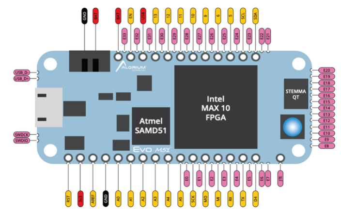
2.2 Digital I/O
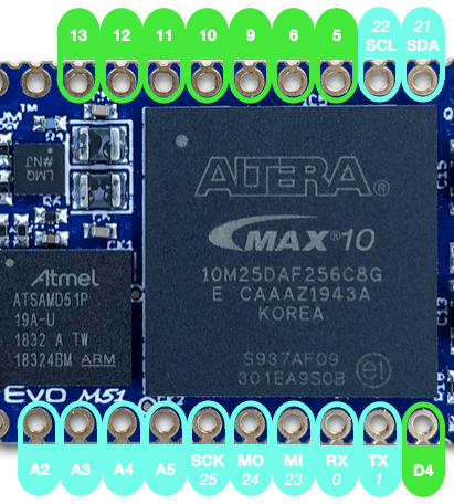
Dedicated Digital GPIO: D4, 5, 6, 9, 10, 11, 12
Pins D4, 5, 6, 9, 10, 11, 12 and 13 provide dedicated digital GPIO pins. In addition, each of these pins can provide PWM outputs.
Additional Digital GPIO
There are a number of additional I/O on Evo assigned to communication interfaces or analog functions that are available as digital I/O:
- RX (0) / TX (1)
- SDA (21) / SCL (22) / SCK (25)
- MO (24) / MI (23)
- A2 /A3 / A4 / A5
2.3 Analog I/O
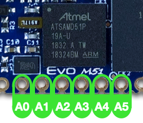
Evo M51 provides access to the ADC and DAC on the SAMD51 microcontroller instead of using the MAX 10 ADC. There are 3 ADC inputs, 2 DAC outputs, and 3 of the analog pins can also be used as digital GPIO.
- A0 / A1
- Analog ADC inputs
- Analog DAC outputs
- A2 – A5
- Analog ADC inputs
- Digital GPIO outputs
- PWM outputs
2.4 E-Pins (Castellated Vias)
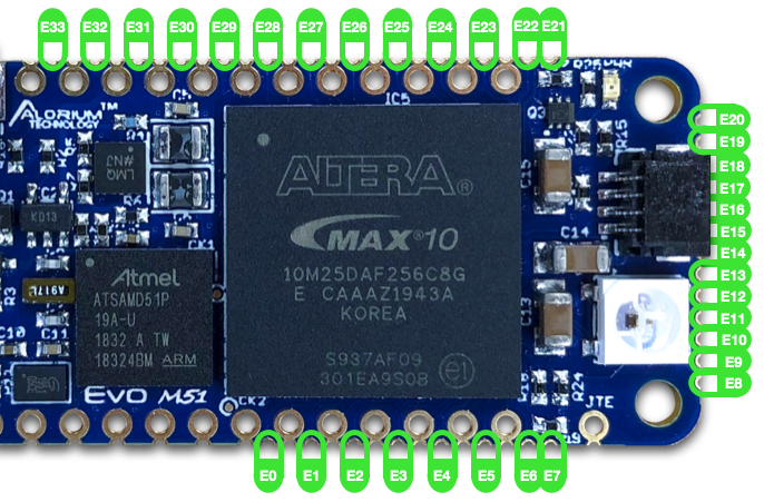
Evo provides an additional 34 digital GPIO through castellated vias (CVs) along the edges of the board.
2.5 Communication Interfaces
- USB_D-/USB_D+ CVs – Differential signal interface to SAMD USB input
- SPI – SPI interface
- SCK – SPI Clock
- MO – Master Out, Slave In (MOSI)
- MI – Master In, Slave Out (MISO)
- I2C – I2C (“Wire”) interface
- SCL – I2C clock
- SDA – I2C data
- Note: SCL/SDA do NOT have on-board pull-up resistors. So, external resistors may be required.
- UART – Serial UART interface
- RX – Receive
- TX – Transmit
- SWD CVs – Single-Wire Debug interface
- SWDCK – SWD Clock
- SWDIO – SWD Data
- JTAG – JTAG programming interface (Shared with GPIO pins 10-13)
- JTE – JTAG Enable
- TCK (12) – Test Clock
- TMS (10) – Test Mode Select
- TDI (11) – Test Data In
- TDO (13) – Test Data Out
2.6 Power, Programming and Other I/O
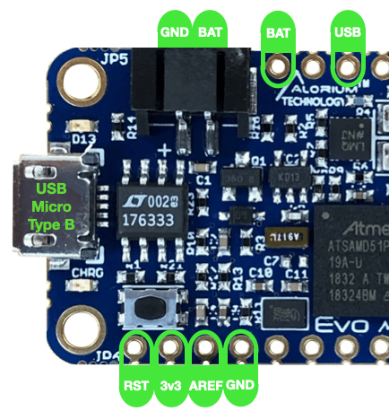
- USB Connector – USB Micro Type B
- RST – SAMD/FPGA Reset
- 3.3V – 3.3V output from voltage regulator
- AREF – Analog reference input (Need details)
- GND – Ground
- JST Battery Connector
- BAT – Positive voltage from battery
- GND – Battery ground
- BAT – Positive voltage from JST Battery connector
- USB – Voltage from USB Micro connector
3 Programming Evo M51
3.1 Programming the SAMD51 Microcontroller
Programming the SAMD51 microcontroller on Evo is easily performed using the very popular Arduino IDE. Refer to Section 4 below for help installing Arduino if you don’t already have it installed on your development machine.
Other programming tools such as Atmel Studio, PlatformIO/VSCode, and others may also work for programming Evo. However, we have not yet validated those solutions, and for now Arduino is the only officially supported programming environment for Evo M51.
3.2 Programming the FPGA
The FPGA on Evo comes pre-programmed with an image that provides simple passthrough functionality.
In time, additional FPGA images with different functionality or new mixes of Xcelerator Blocks will be available from Alorium Technology. Those images can be uploaded directly through the Arduino IDE or accessed via our GitHub repo and flashed to the FPGA using a command-line program.
As with all of our products, the FPGA can be programmed with your own custom FPGA image by using our OpenEvo FPGA methodology.
3.3 CircuitPython
Evo M51 is designed to support CircuitPython – a special version of the Python programming language designed to run on microcontrollers. CircuitPython uses a slightly different development flow than programming standard C programs or Arduino sketches.
4 Installing the Arduino IDE
4.1 Arduino IDE Software Installation for Microsoft Windows and macOS
The first step in setting up your computer to connect to and program the Snō is to install the standard Arduino IDE software. Follow the instructions below to install the Arduino IDE on your computer.
Microsoft Windows
- Click here for the official Arduino IDE installation guide for Microsoft Windows.
- Follow the instructions for installing the IDE.
- Once the IDE is installed, return here to finish installation of the Alorium Technology board specific packages and libraries.
Mac OS X
- Click here for the official Arduino IDE installation guide for Mac OS X.
- Follow the instructions for installing the IDE.
- Once the IDE is installed, return here to finish installation of the Alorium Technology board specific packages and libraries.
Linux
If you are running Linux, the setup steps are a bit different. Therefore, we have created one tutorial that incorporates all of the steps Linux requires to setup Arduino IDE.
This document was originally created when we released our XLR8 board, and it still carries the XLR8 name in the title. However, the steps remain the same for using Arduino with Evo, as well.
Click the link below to see our Linux Setup Tutorial:
5 Evo M51 Board Package and Libraries
5.1 Add Evo M51 Board Support
Open the Arduino IDE and follow these steps to add board support in the Arduino IDE.
- For Windows and LInux: Go to File > Preferences, in your Arduino IDE menu bar.
- For Mac: Go to Arduino > Preferences, in your Arduino IDE menu bar.
- Locate the ‘Additional Boards Manager URLs’ input field.
- Copy and paste this URL into the “Additional Boards Manager URLs” input field
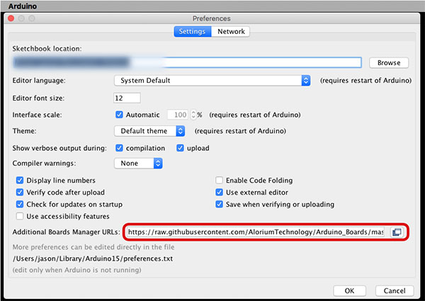
Note: Multiple URLs can be added to this field by separating each URL with a comma.
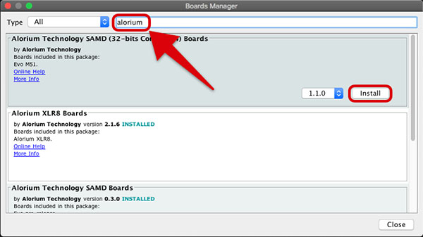
Install Alorium’s Evo M51 board package
- Go to Tools > Board > Boards Manager.
- Type “alorium,” in the search field and you will see an option to install board files for Alorium SAMD compatible boards.
- Select the “Alorium Technology SAMD (32-bits Cortex-M4) Boards” package and then click “Install.”
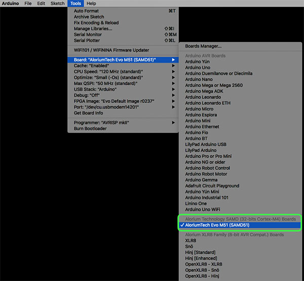
Select the Evo M51 Board
- Go to Tools > Board. You should see a new section titled “Alorium Technology SAMD (32-bits Cortex-M4) Boards” now exists.
- Select “AloriumTech Evo M51 (SAMD51) board.
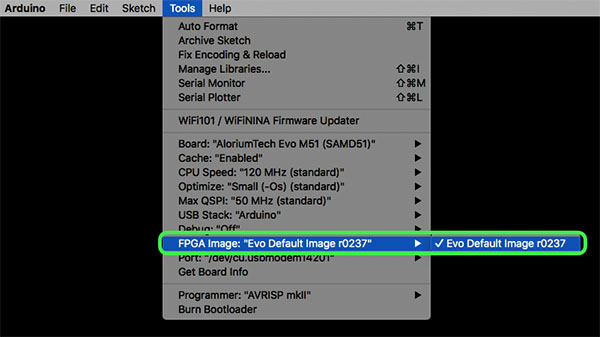
After selecting Evo M51, you will find a new menu item at Tools > FPGA Image, where you will see the list of released Evo M51 FPGA images that are packaged with the Arduino IDE.
5.2 Evo M51 Libraries
All libraries required to use Evo M51 are packaged with the Alorium Technology SAMD Arduino board package.
As new functionality or Xcelerator Blocks (XBs) are added for the FPGA, new libraries may be released. Detailed instructions for installing required libraries will be added at that time.
5.3 Running an Example Sketch/Program
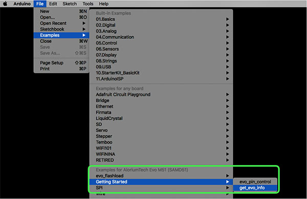
To be sure that everything is installed and working correctly, we have provided an example Arduino sketch called “get_evo_info” that you can load from the Arduino IDE Examples menu.
- Be sure that your Evo board is connected to your computer with a USB cable.
- Go to Tools > Board and select AloriumTech Evo M51 (SAMD51)
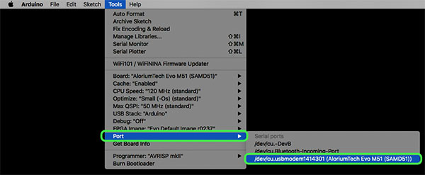
- Be sure to select the correct port from Tools > Port:
- Go to File > Examples > Examples for AloriumTech Evo M51 (SAMD51) > Getting Started and select get_evo_info
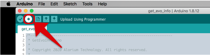
- In the get_evo_info sketch window, click on the Upload button
- Check the Serial Monitor window for the output, which should look like the output below. Note that you will need to set the baud rate for the Serial Monitor to 115200 for this sketch to display output correctly.
==================================
Start: get_evo_info
==================================
Product: EM51
Board Revision: 202002
----------------------------------
FPGA: 10M25
FPGA Release: 1
FPGA SVN: 237
----------------------------------
Xcelerator Block Config:
Number of XBs: 0
==================================
End: get_evo_info
==================================
5.5 Congratulations!
If you get this output from get_evo_info, that means everything is installed correctly, and the SAMD51 is talking to the FPGA! Congratulations! Now it’s time to start building cool projects with your Evo M51.
6 Running CircuitPython
A Note on CircuitPython Readiness….
CircuitPyton is only partially supported at this time. Since the I/O on Evo is routed through the FPGA, additional code is required “under the covers” to appropriately configure the I/O on the FPGA to correspond with I/O settings on the SAMD51.
In the Arduino world, we have handled this with libraries that abstract and hide the mechanics of this process, and we have started to implement similar support libraries for CircuitPython, as well. However, that effort is not complete. We’ll continue to update our docs and libraries as the developments mature.
6.1 What’s CircuitPython?
Evo M51 is designed to support CircuitPython – a special version of the Python programming language designed to run on microcontrollers. CircuitPython was created by Adafruit Industries who continues to support, improve and promote CiruitPython development.
You can learn more about CircuitPython here: https://circuitpython.org/
Adafruit also sells a truckload of very cool products, many of which we frequently use alongside our FPGA boards, so be sure to check out their website.
6.2 Installing CircuitPython
1. Download AloroiumTech Evo M51 CircuitPython .UF2
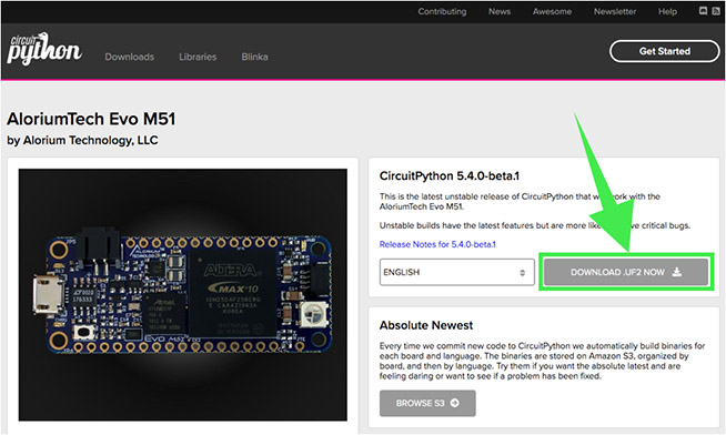
The first step toward using CircuitPython with Evo is to install the CircuitPython bootloader which comes in the form of a .UF2 or “UF2” file. The UF2 can be downloaded from the Evo M51 page on the CircuitPythyon.org website.
Click here to be taken to the page.
Once there, click on the “DOWNLOAD .UF2 NOW” button:
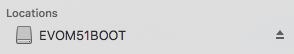
2. Plug in your Evo board and double-click the Reset button
Double-clicking the Reset button will put it into Bootloader mode, and it shoudl now show up with the label “EVOM51BOOT”:
3. Drag UF2 file to EVOM51BOOT drive
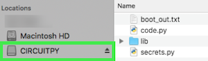
Now, you can simply drag the UF2 file that you dowloaded in Step 1 above on to the EVOM51BOOT drive. Once that is done, the board will reboot, and when it comes back up, it should be labeled “CIRCUITPY”.
CircuitPython is now up and running!
6.3 Running a CircuitPython Example
There are a small number of CircuitPython examples that will work with Evo M51 avaiable on GitHub here:
AloriumTech CircuitPython EvoM51 Examples
Just like with Arduino, we provide a CircuitPython program named “get_evo_info.py” that will query the FPGA and print out the information.
Follow these steps to run this example:
1. Download the file from our GitHub repository
2. Copy get_evo_info.py to the CIRCUITPY drive and rename to “code.py”
You should see the following output:
code.py output:
==================================
Start: get_evo_info
==================================
Product: EM51
Board Revision: 202002
----------------------------------
FPGA: 10M25
FPGA Release: 01
FPGA SVN: 237
----------------------------------
Xcelerator Block Config
Number of XBs: 0
==================================
End: get_evo_info
==================================
7 Updating the FPGA Image
Evo M51 ships with a “passthrough” image loaded on to the FPGA. Essentially, this just means that all of board I/O – minus the shared analog signals – are routed through the FPGA to the through-hole and castellated vias.
This image can be updated with other images provided by Alorium Technology by using the Arduino IDE to load a sketch and then running a standalone command-line program.
For a short video tutorial of how you can upload a new image to the FPGA using the Arduino + command-line method, click below:
This process will soon be replaced with a single command-line tool that eliminates the need to also run the Arduino IDE. Here’s a video from our YouTube VLOG showing some testing of the new functionality which will be released in July 2020.
8 Restoring Factory FPGA Image
The FPGA on Evo can hold two different FPGA images. One of those, Image 1, can be reconfigured with new images to take advantage of increased functionality as new features are introduced and released. This process is done via the steps defined in Section 7 above.
The other image, Image 0, is never changed, and is typically unused unless the primary image 1 becomes corrupted. If necessary, a “factory reset” of Evo M51 can be performed by grounding the FPGA side of R19 while applying power to the board.
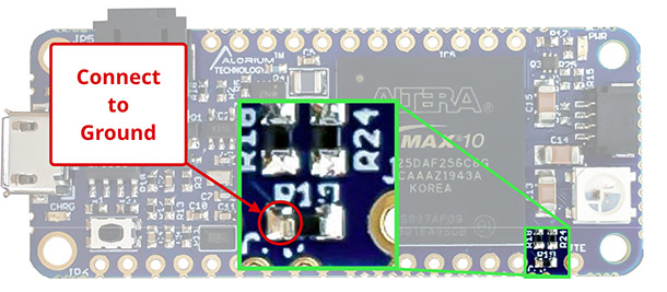
It only takes a momentary grounding to cause this to happen. The factory image is then loaded. Any loss of power to the board will still cause the corrupted image to be reloaded, however.
Once the FPGA has loaded Image 0, you should load a known, good image back into the Image 1 location following the process defined in Section 7.
9 Schematic
View schematics and layout here: Evo M51 Schematic
10 Register Summary
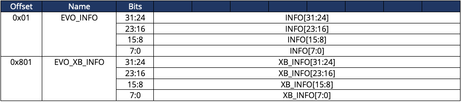
10.1 Info Registers Base Address
10.2 Info Registers Map
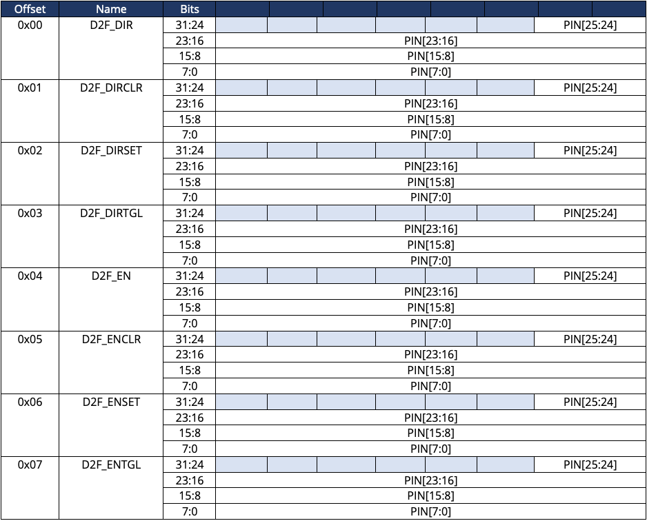
10.3 D2F Registers Base Address
10.4 D2F Registers Map
10.5 Port D Registers Base Address
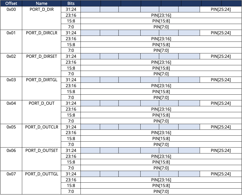
10.6 Port D Registers Map
10.7 Port E Registers Base Address
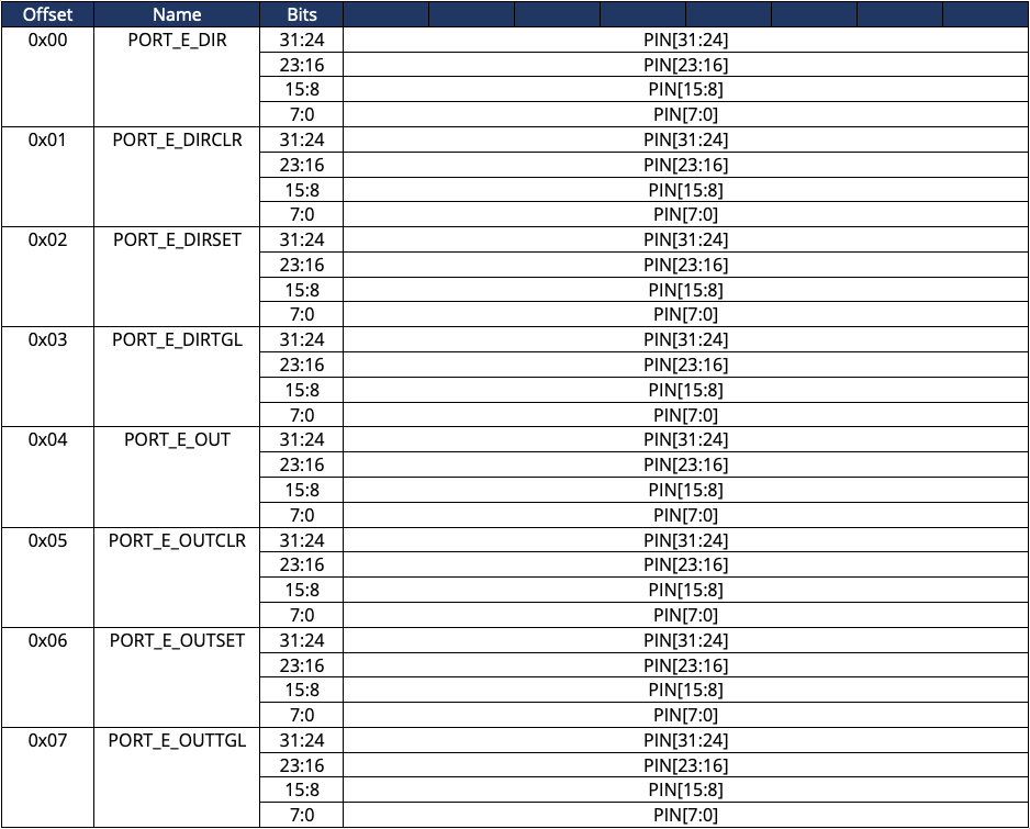
10.8 Port E Registers Map
10.9 Port F Registers Base Address
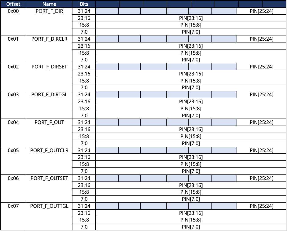
10.10 Port F Registers Map
10.11 Port G Registers Base Address
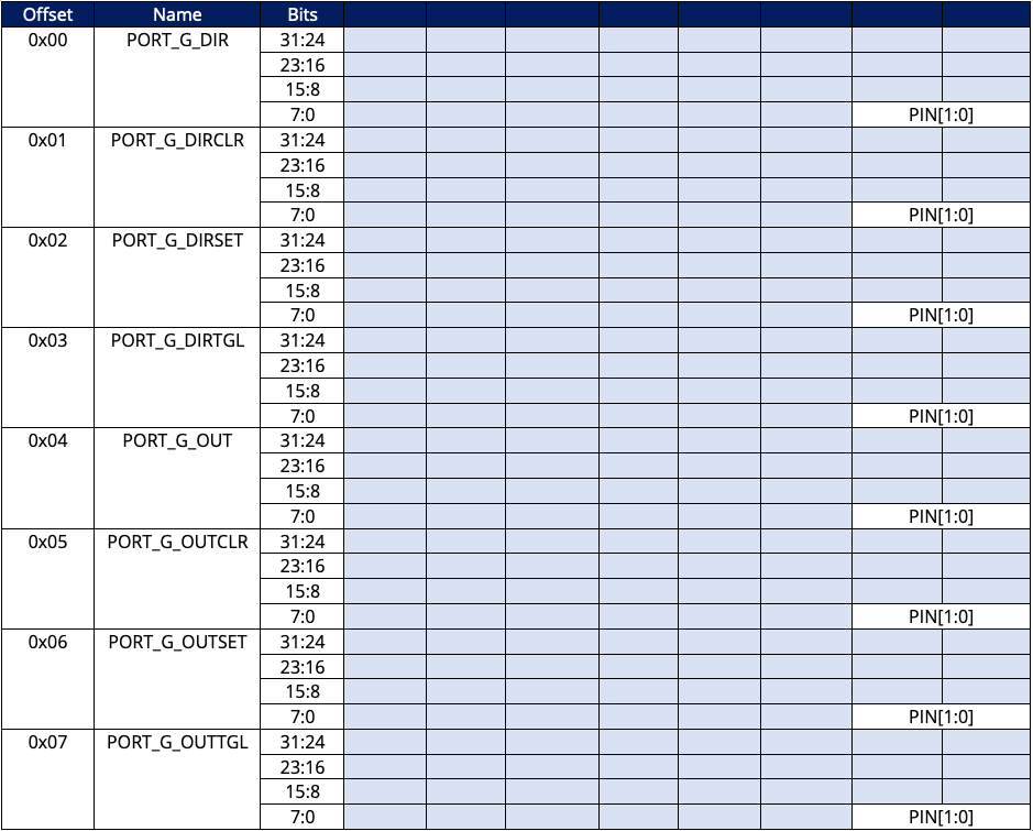
10.12 Port G Registers Map
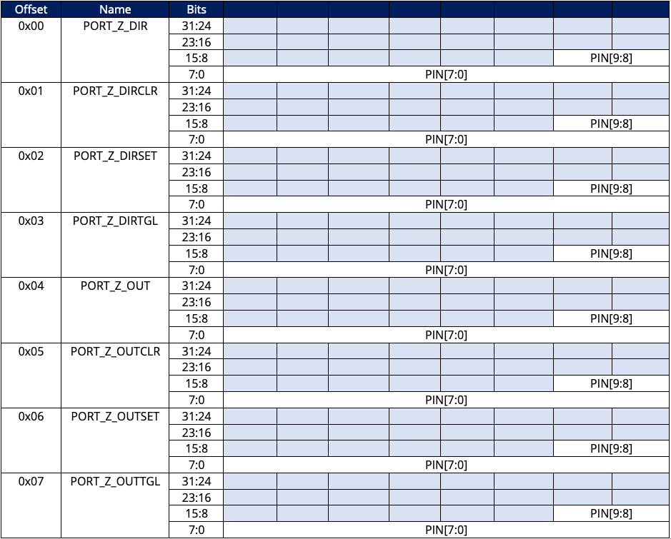
10.13 Port Z Registers Base Address

10.14 Port Z Registers Map
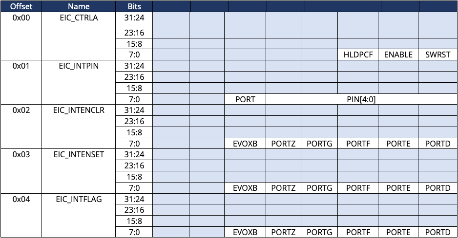
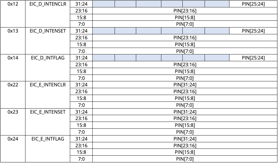
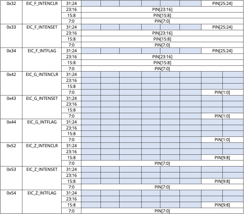
10.15 Interrupt Registers Base Address
10.16 Interrupt Registers Map
Your Feedback Helps!
If you see anything that does not make sense, or want specific information that we have not yet posted, please feel free to email us at: support@aloriumtech.com.
Thanks!
Improve Your Project!
Alorium Technology | 3041 Melby St., Eau Claire, WI 54703 | 715-575-3150